1. 4-row circular arc groove type 2-point contact guide that is resistant to large moment load is adopted.Note 1
Basic Info
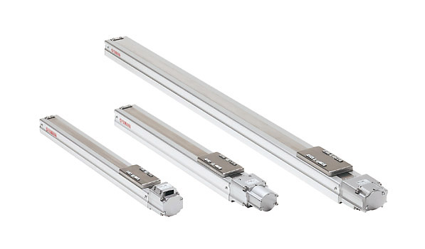
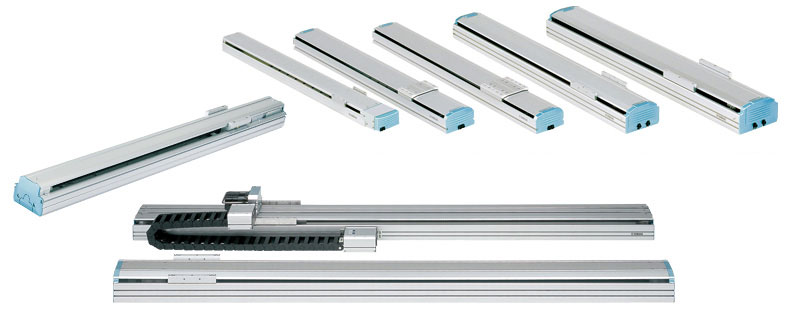
Double appeal of a compact body and low price.
Ideal in applications as an actuator directly installed on a mount.
- Stroke : 50 to 1050mm
- Maximum speed : 120 to 1800mm/sec
- Maximum payload(Horizontal) : 3 to 100kg
Feature
4-row circular arc groove type 2-point contact guide with less differential slip is used for the linear guide. This guide has less ball differential slip due to its structure when compared to the 2-row Gothic arch type 4-point contact guide and maintains a satisfactory rolling movement even if a large moment load is applied or the installation surface precision is poor. The guide has characteristics that are difficult to malfunction, such as unusual wear and provides excellent reliability.
● F/N/B typeNote 2
For the F type, N type, and B type, two guide frames are laid out on the high rigidity aluminum extruded material frame. Two bearing units per rail, four bearing units in total, support a large load firmly. As a large moment load is mainly converted into vertical force, the moment applied to one bearing unit becomes small to ensure excellent durability.
- F8 series
The F8 series uses a newly developed module guide to greatly reduce the crosssectional area (70 % when compared to F10). The rail is laid out in the full width of the frame to ensure the high rigidity even with compact design. Of course, this series also uses the 4-row circular arc groove type 2-point contact guide.
Note 1. Note 1. Except for T4L/T4LH and T5L/T5LH
Note 2. Except for F8 series/F10/B10.
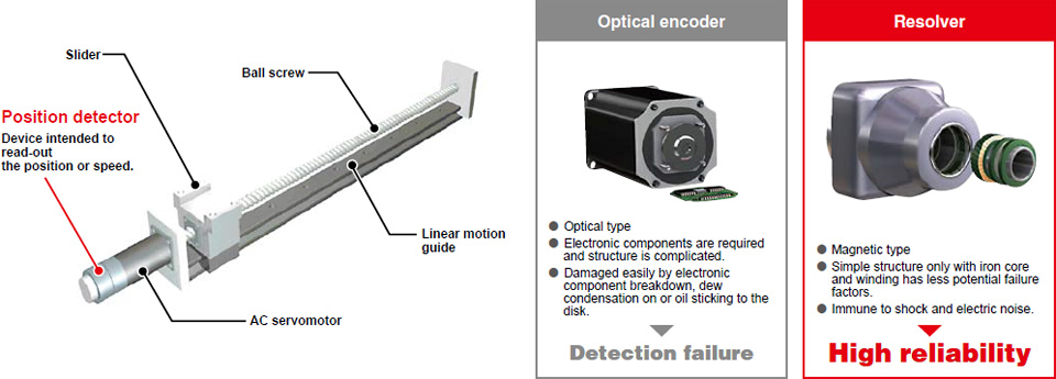
2. Resolver with excellent environment resistance is used for the position detector.
A resolver is used for the position detector. The resolver has a simple and rigid structure without using electronic components and optical elements. Detection problems due to electronic component breakdown, dew condensation on or oil sticking to the disk that may occur in optical encoders do not occur in the resolver. The resolver provides excellent durability. Additionally, as the absolute specifications and incremental specifications use the same mechanical specifications and common controller, desired specifications can be selected only by setting parameters. Furthermore, even when the absolute battery is consumed completely, the robot can still operate as the incremental specifications. So, even if a trouble occurs, the line stop is not needed to ensure the safe production line. Furthermore, the backup circuit has been completely renovated and now has a backup period of one year in the non-energizing state.
3. Long service life greatly reduces the maintenance cost.
As the acceleration is determined by the weight parameter, the service life can be assured when the weight and position of center of gravity are known.
YAMAHA’s robot uses high rigidity ball screw or guide, it provides excellent durability. This greatly contributes to reduction of the customer’s maintenance cost.
4. Controllers suitable for applications are prepared.
In addition to the robot program operation and pulse train control, a positioner that is operated by specifying a point number was added to the product lineup. Additionally, multi specifications that control multiple robots using one controller are also supported. You can select an optimal controller suitable for your application.
5. Various custom specifications are supported.
YAMAHA supports custom orders flexibility to meet the customers’ various needs.
| Addition of free slider | Free slider is added. Various applications, such as rigidity increase or use of two heads are supported. |
|---|---|
| Wide slider | To increase the slider rigidity, the standard slider is processed to the wide slider. |
| Specified stroke | A stroke smaller than the minimum stroke may be supported. For details, please consult YAMAHA. |
| Lead beyond catalog | The lead may be changed to that not stated in the catalog. For details, please consult YAMAHA. |
| Origin non-motor specifications | Even when not stated in the catalog, the origin may be changed to the non-motor side. For details, please consult YAMAHA. |
YAMAHA has a wide variety of custom order results other than those shown above.
If you have any requirement or request, please feel free to contact us
Specification
| Model | Size (mm) | Lead (mm) | Maximum payload (kg) | Maximum speed (mm/sec) | Stroke (mm) | |
|---|---|---|---|---|---|---|
| Horizontal | Vertical | |||||
T4L T4LH | W45×H53 | 12 | 4.5 | 1.2 | 720 | 50 to 400 |
| 6 | 6 | 2.4 | 360 | |||
| 2 | 6 | 7.2 | 120 | |||
T5L T5LH | W55×H52 | 20 | 3 | – | 1200 | 50 to 800 |
| 12 | 5 | 1.2 | 800 | |||
| 6 | 9 | 2.4 | 400 | |||
T6L | W65×H56 | 20 | 10 | – | 1333 | 50 to 800 |
| 12 | 12 | 4 | 800 | |||
| 6 | 30 | 8 | 400 | |||
| T9 (Standard) | W94×H98 | 30 | 15 | – | 1800 | 150 to 1050 |
| 20 | 30 | 4 | 1200 | |||
| 10 | 55 | 10 | 600 | |||
| 5 | 80 | 20 | 300 | |||
| T9H (High Thrust) | 30 | 25 | – | 1800 | ||
| 20 | 40 | 8 | 1200 | |||
| 10 | 80 | 20 | 600 | |||
| 5 | 100 | 30 | 300 | |||
Note1. Size is the approximate cross sectional size.
Basic Info
Large inertial moment capacity, easily handles offset loads.
Ideal for Cartesian robots requiring arm strength, and for moving arms that shift the entire axis.
- Stroke : 150 to 2050mm
- Maximum speed : 300 to 2400mm/sec
- Maximum payload(Horizontal) : 7 to 120kg
Feature
1. 4-row circular arc groove type 2-point contact guide that is resistant to large moment load is adopted.Note 1
4-row circular arc groove type 2-point contact guide with less differential slip is used for the linear guide. This guide has less ball differential slip due to its structure when compared to the 2-row Gothic arch type 4-point contact guide and maintains a satisfactory rolling movement even if a large moment load is applied or the installation surface precision is poor. The guide has characteristics that are difficult to malfunction, such as unusual wear and provides excellent reliability.
● F/N/B typeNote 2
For the F type, N type, and B type, two guide frames are laid out on the high rigidity aluminum extruded material frame. Two bearing units per rail, four bearing units in total, support a large load firmly. As a large moment load is mainly converted into vertical force, the moment applied to one bearing unit becomes small to ensure excellent durability.
- F8 series
The F8 series uses a newly developed module guide to greatly reduce the crosssectional area (70 % when compared to F10). The rail is laid out in the full width of the frame to ensure the high rigidity even with compact design. Of course, this series also uses the 4-row circular arc groove type 2-point contact guide.
Note 1. Note 1. Except for T4L/T4LH and T5L/T5LH
Note 2. Except for F8 series/F10/B10.
2. Resolver with excellent environment resistance is used for the position detector.
A resolver is used for the position detector. The resolver has a simple and rigid structure without using electronic components and optical elements. Detection problems due to electronic component breakdown, dew condensation on or oil sticking to the disk that may occur in optical encoders do not occur in the resolver. The resolver provides excellent durability. Additionally, as the absolute specifications and incremental specifications use the same mechanical specifications and common controller, desired specifications can be selected only by setting parameters. Furthermore, even when the absolute battery is consumed completely, the robot can still operate as the incremental specifications. So, even if a trouble occurs, the line stop is not needed to ensure the safe production line. Furthermore, the backup circuit has been completely renovated and now has a backup period of one year in the non-energizing state.
3. Long service life greatly reduces the maintenance cost.
As the acceleration is determined by the weight parameter, the service life can be assured when the weight and position of center of gravity are known.
YAMAHA’s robot uses high rigidity ball screw or guide, it provides excellent durability. This greatly contributes to reduction of the customer’s maintenance cost.
4. Controllers suitable for applications are prepared.
In addition to the robot program operation and pulse train control, a positioner that is operated by specifying a point number was added to the product lineup. Additionally, multi specifications that control multiple robots using one controller are also supported. You can select an optimal controller suitable for your application.
5. Various custom specifications are supported.
YAMAHA supports custom orders flexibility to meet the customers’ various needs.
| Addition of free slider | Free slider is added. Various applications, such as rigidity increase or use of two heads are supported. |
|---|---|
| Wide slider | To increase the slider rigidity, the standard slider is processed to the wide slider. |
| Specified stroke | A stroke smaller than the minimum stroke may be supported. For details, please consult YAMAHA. |
| Lead beyond catalog | The lead may be changed to that not stated in the catalog. For details, please consult YAMAHA. |
| Origin non-motor specifications | Even when not stated in the catalog, the origin may be changed to the non-motor side. For details, please consult YAMAHA. |
YAMAHA has a wide variety of custom order results other than those shown above.
If you have any requirement or request, please feel free to contact us
Specification
| Model | Size (mm) | Lead (mm) | Maximum payload (kg) | Maximum speed (mm/sec) | Stroke (mm) | |
|---|---|---|---|---|---|---|
| Horizontal | Vertical | |||||
| F8 | W80×H65 | 20 | 12 | – | 1200 | 150 to 800 |
| 12 | 20 | 4 | 720 | |||
| 6 | 40 | 8 | 360 | |||
| F8L | W80×H65 | 30 | 7 | – | 1800 | 150 to 1050 |
| 20 | 20 | 4 | 1200 | |||
| 10 | 40 | 8 | 600 | |||
| 5 | 50 | 16 | 300 | |||
F8LH | 20 | 30 | – | 1200 | ||
| 10 | 60 | – | 600 | |||
| 5 | 80 | – | 300 | |||
| 30 | 15 | – | 1800 | 150 to 1050 | ||
| 20 | 20 | 4 | 1200 | |||
| 10 | 40 | 10 | 600 | |||
| 5 | 60 | 20 | 300 | |||
| F10H(High thrust) | 30 | 25 | – | 1800 | 150 to 1000 | |
| 20 | 40 | 8 | 1200 | |||
| 10 | 80 | 20 | 600 | |||
| 5 | 100 | 30 | 300 | |||
| F14(Standard) | W136×H83 | 30 | 15 | – | 1800 | 150 to 1050 |
| 20 | 30 | 4 | 1200 | |||
| F14H(High thrust) | 10 | 55 | 10 | 600 | ||
| 5 | 80 | 20 | 300 | |||
| F17L | W168×H100 | 50 | 50 | 10 | 2200 | 100 to 2050 |
| F17 | 40 | 40 | – | 2400 | 200 to 1450 | |
| 20 | 80 | 15 | 1200 | 200 to 1250 | ||
| 10 | 120 | 35 | 600 | |||
| F20 | W202×H115 | 40 | 60 | – | 2400 | 200 to 1450 |
| 20 | 120 | 25 | 1200 | 200 to 1250 | ||
| 10 | – | 45 | 600 | |||
| F20N | W202×H120 | 20 | 80 | – | 1200 | 1150 to 2050 |
- Note1. Size is the approximate cross sectional size.

Basic Info
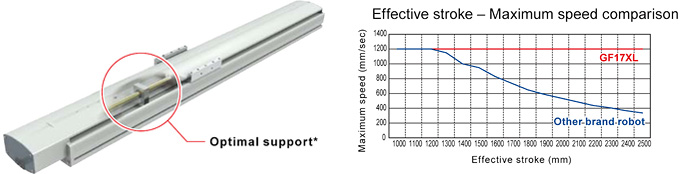
Maximum velocity throughout the full range of stroke with no speed deration
- Stroke : 750 to 2500mm
- Maximum speed : 1200mm/sec
- Repetability : +/-0.01mm
- Maximum payload : 90kg
Feature
Multiple “optimal supports”* eliminate speed deration

Equipped with YAMAHA’s “optimal supports”* at multiple points to ensure optimal ball screw support.
*Patent pending
1. 4-row circular arc groove type 2-point contact guide that is resistant to large moment load is adopted.Note 1
4-row circular arc groove type 2-point contact guide with less differential slip is used for the linear guide. This guide has less ball differential slip due to its structure when compared to the 2-row Gothic arch type 4-point contact guide and maintains a satisfactory rolling movement even if a large moment load is applied or the installation surface precision is poor. The guide has characteristics that are difficult to malfunction, such as unusual wear and provides excellent reliability.
● F/N/B typeNote 2
For the F type, N type, and B type, two guide frames are laid out on the high rigidity aluminum extruded material frame. Two bearing units per rail, four bearing units in total, support a large load firmly. As a large moment load is mainly converted into vertical force, the moment applied to one bearing unit becomes small to ensure excellent durability.
- F8 series
The F8 series uses a newly developed module guide to greatly reduce the crosssectional area (70 % when compared to F10). The rail is laid out in the full width of the frame to ensure the high rigidity even with compact design. Of course, this series also uses the 4-row circular arc groove type 2-point contact guide.
Note 1. Note 1. Except for T4L/T4LH and T5L/T5LH
Note 2. Except for F8 series/F10/B10.
2. Resolver with excellent environment resistance is used for the position detector.
A resolver is used for the position detector. The resolver has a simple and rigid structure without using electronic components and optical elements. Detection problems due to electronic component breakdown, dew condensation on or oil sticking to the disk that may occur in optical encoders do not occur in the resolver. The resolver provides excellent durability. Additionally, as the absolute specifications and incremental specifications use the same mechanical specifications and common controller, desired specifications can be selected only by setting parameters. Furthermore, even when the absolute battery is consumed completely, the robot can still operate as the incremental specifications. So, even if a trouble occurs, the line stop is not needed to ensure the safe production line. Furthermore, the backup circuit has been completely renovated and now has a backup period of one year in the non-energizing state.
3. Long service life greatly reduces the maintenance cost.
As the acceleration is determined by the weight parameter, the service life can be assured when the weight and position of center of gravity are known.
YAMAHA’s robot uses high rigidity ball screw or guide, it provides excellent durability. This greatly contributes to reduction of the customer’s maintenance cost.
4. Controllers suitable for applications are prepared.
In addition to the robot program operation and pulse train control, a positioner that is operated by specifying a point number was added to the product lineup. Additionally, multi specifications that control multiple robots using one controller are also supported. You can select an optimal controller suitable for your application.
5. Various custom specifications are supported.
YAMAHA supports custom orders flexibility to meet the customers’ various needs.
| Addition of free slider | Free slider is added. Various applications, such as rigidity increase or use of two heads are supported. |
|---|---|
| Wide slider | To increase the slider rigidity, the standard slider is processed to the wide slider. |
| Specified stroke | A stroke smaller than the minimum stroke may be supported. For details, please consult YAMAHA. |
| Lead beyond catalog | The lead may be changed to that not stated in the catalog. For details, please consult YAMAHA. |
| Origin non-motor specifications | Even when not stated in the catalog, the origin may be changed to the non-motor side. For details, please consult YAMAHA. |
YAMAHA has a wide variety of custom order results other than those shown above.
If you have any requirement or request, please feel free to contact us
Specification
| Model | Size (mm) | Lead (mm) | Maximum payload (kg) | Maximum speed (mm/sec) | Stroke (mm) | |
|---|---|---|---|---|---|---|
| Horizontal | Vertical | |||||
| GF14XL | W140×H91.5 | 20 | 45 | – | 1200 | 750 to 2000 |
| GF17XL | W168×H105.5 | 20 | 90 | – | 1200 | 850 to 2500 |
Note1. Size is the approximate cross sectional size

Basic Info
Maximum stroke length of 3050mm. Allows long distance transport between job processes.
- Stroke : 150 to 3050mm
- Maximum speed : 1875mm
- Maximum payload : 10 to 30kg
Feature
1. 4-row circular arc groove type 2-point contact guide that is resistant to large moment load is adopted.Note 1
4-row circular arc groove type 2-point contact guide with less differential slip is used for the linear guide. This guide has less ball differential slip due to its structure when compared to the 2-row Gothic arch type 4-point contact guide and maintains a satisfactory rolling movement even if a large moment load is applied or the installation surface precision is poor. The guide has characteristics that are difficult to malfunction, such as unusual wear and provides excellent reliability.
● F/N/B typeNote 2
For the F type, N type, and B type, two guide frames are laid out on the high rigidity aluminum extruded material frame. Two bearing units per rail, four bearing units in total, support a large load firmly. As a large moment load is mainly converted into vertical force, the moment applied to one bearing unit becomes small to ensure excellent durability.
- F8 series
The F8 series uses a newly developed module guide to greatly reduce the crosssectional area (70 % when compared to F10). The rail is laid out in the full width of the frame to ensure the high rigidity even with compact design. Of course, this series also uses the 4-row circular arc groove type 2-point contact guide.
Note 1. Note 1. Except for T4L/T4LH and T5L/T5LH
Note 2. Except for F8 series/F10/B10.
2. Resolver with excellent environment resistance is used for the position detector.
A resolver is used for the position detector. The resolver has a simple and rigid structure without using electronic components and optical elements. Detection problems due to electronic component breakdown, dew condensation on or oil sticking to the disk that may occur in optical encoders do not occur in the resolver. The resolver provides excellent durability. Additionally, as the absolute specifications and incremental specifications use the same mechanical specifications and common controller, desired specifications can be selected only by setting parameters. Furthermore, even when the absolute battery is consumed completely, the robot can still operate as the incremental specifications. So, even if a trouble occurs, the line stop is not needed to ensure the safe production line. Furthermore, the backup circuit has been completely renovated and now has a backup period of one year in the non-energizing state.
3. Long service life greatly reduces the maintenance cost.
As the acceleration is determined by the weight parameter, the service life can be assured when the weight and position of center of gravity are known.
YAMAHA’s robot uses high rigidity ball screw or guide, it provides excellent durability. This greatly contributes to reduction of the customer’s maintenance cost.
4. Controllers suitable for applications are prepared.
In addition to the robot program operation and pulse train control, a positioner that is operated by specifying a point number was added to the product lineup. Additionally, multi specifications that control multiple robots using one controller are also supported. You can select an optimal controller suitable for your application.
5. Various custom specifications are supported.
YAMAHA supports custom orders flexibility to meet the customers’ various needs.
| Addition of free slider | Free slider is added. Various applications, such as rigidity increase or use of two heads are supported. |
|---|---|
| Wide slider | To increase the slider rigidity, the standard slider is processed to the wide slider. |
| Specified stroke | A stroke smaller than the minimum stroke may be supported. For details, please consult YAMAHA. |
| Lead beyond catalog | The lead may be changed to that not stated in the catalog. For details, please consult YAMAHA. |
| Origin non-motor specifications | Even when not stated in the catalog, the origin may be changed to the non-motor side. For details, please consult YAMAHA. |
YAMAHA has a wide variety of custom order results other than those shown above.
If you have any requirement or request, please feel free to contact us
Specification
| Model | Size (mm) | Lead (mm) | Maximum payload (kg) | Maximum speed (mm/sec) | Stroke (mm) | |
|---|---|---|---|---|---|---|
| Horizontal | Vertical | |||||
| B10 | W100×H81 | Belt drive | 10 | – | 1875 | 150 to 2550 |
| B14 (Standard) | W146×H94 | Belt drive | 20 | – | 1875 | 150 to 3050 |
| B14H (High thrust) | 30 | – | ||||
- Note1.
- Size is the approximate cross sectional size.
Basic Info
The critical speed is not restricted. This ensures a high-speed transfer.
- Stroke : 250 to 2500mm
- Maximum speed : 1200mm/sec
- Repeatability : +/-0.01mm
- Maximum payload : 50 to 80kg
Feature
1. 4-row circular arc groove type 2-point contact guide that is resistant to large moment load is adopted.Note 1
4-row circular arc groove type 2-point contact guide with less differential slip is used for the linear guide. This guide has less ball differential slip due to its structure when compared to the 2-row Gothic arch type 4-point contact guide and maintains a satisfactory rolling movement even if a large moment load is applied or the installation surface precision is poor. The guide has characteristics that are difficult to malfunction, such as unusual wear and provides excellent reliability.
● F/N/B typeNote 2
For the F type, N type, and B type, two guide frames are laid out on the high rigidity aluminum extruded material frame. Two bearing units per rail, four bearing units in total, support a large load firmly. As a large moment load is mainly converted into vertical force, the moment applied to one bearing unit becomes small to ensure excellent durability.
- F8 series
The F8 series uses a newly developed module guide to greatly reduce the crosssectional area (70 % when compared to F10). The rail is laid out in the full width of the frame to ensure the high rigidity even with compact design. Of course, this series also uses the 4-row circular arc groove type 2-point contact guide.
Note 1. Note 1. Except for T4L/T4LH and T5L/T5LH
Note 2. Except for F8 series/F10/B10.
2. Resolver with excellent environment resistance is used for the position detector.
A resolver is used for the position detector. The resolver has a simple and rigid structure without using electronic components and optical elements. Detection problems due to electronic component breakdown, dew condensation on or oil sticking to the disk that may occur in optical encoders do not occur in the resolver. The resolver provides excellent durability. Additionally, as the absolute specifications and incremental specifications use the same mechanical specifications and common controller, desired specifications can be selected only by setting parameters. Furthermore, even when the absolute battery is consumed completely, the robot can still operate as the incremental specifications. So, even if a trouble occurs, the line stop is not needed to ensure the safe production line. Furthermore, the backup circuit has been completely renovated and now has a backup period of one year in the non-energizing state.
3. Long service life greatly reduces the maintenance cost.
As the acceleration is determined by the weight parameter, the service life can be assured when the weight and position of center of gravity are known.
YAMAHA’s robot uses high rigidity ball screw or guide, it provides excellent durability. This greatly contributes to reduction of the customer’s maintenance cost.
4. Controllers suitable for applications are prepared.
In addition to the robot program operation and pulse train control, a positioner that is operated by specifying a point number was added to the product lineup. Additionally, multi specifications that control multiple robots using one controller are also supported. You can select an optimal controller suitable for your application.
5. Various custom specifications are supported.
YAMAHA supports custom orders flexibility to meet the customers’ various needs.
| Addition of free slider | Free slider is added. Various applications, such as rigidity increase or use of two heads are supported. |
|---|---|
| Wide slider | To increase the slider rigidity, the standard slider is processed to the wide slider. |
| Specified stroke | A stroke smaller than the minimum stroke may be supported. For details, please consult YAMAHA. |
| Lead beyond catalog | The lead may be changed to that not stated in the catalog. For details, please consult YAMAHA. |
| Origin non-motor specifications | Even when not stated in the catalog, the origin may be changed to the non-motor side. For details, please consult YAMAHA. |
YAMAHA has a wide variety of custom order results other than those shown above.
If you have any requirement or request, please feel free to contact us
6. N type structure
In this structure, movement is via a nut that rotates while clamped to a screw shaft, the ball screw nut is linked to the hollow motor.
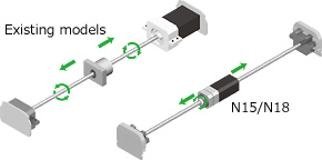
7. A high-speed transfer is possible even with a long stroke.
As the ball screw does not rotate, the critical speed is not restricted.
This ensures a high-speed transfer even with a long stroke.
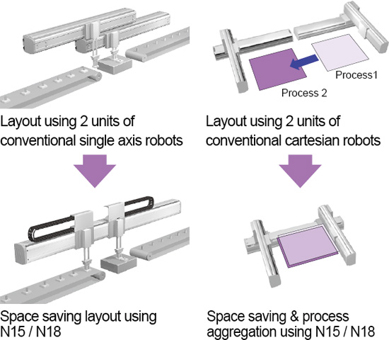
8. Double carrier available as a standard
Two carriers can be arranged co axially by utilizing the features of the nut rotation type.
Space saving and cost reduction can be achieved when compared to use of two single axis robots.
Specification
| Model | Size (mm) | Lead (mm) | Maximum payload (kg) | Maximum speed (mm/sec) | Stroke (mm) | |
|---|---|---|---|---|---|---|
| Horizontal | Vertical | |||||
N15(Single carriage) | W145 × H120 | 20 | 50 | – | 1200 | 500 to 2000 |
N15D(Double carriage) | – | 250 to 1750 | ||||
N18(Single carriage) | W180 × H115 | 80 | – | 500 to 2500 | ||
N18D(Double carriage) | – | 250 to 2250 | ||||
Note1. Size is the approximate cross sectional size.
Basic Info
Position repeatability accuracy of +/-30 seconds (0.0083°).
The R type can be used as the rotation axis when combined with other robots, or utilized for a wide range of applications such as index tables.
Harmonic drive delivers high-strength and high-accuracy.
- Rotation range : 360°
- Maximum speed : 360°/sec
- Maximum allowable moment inertia : 0.12 to 1.83kgm2
Feature
1. Resolver with excellent environment resistance is used for the position detector.
A resolver is used for the position detector. The resolver has a simple and rigid structure without using electronic components and optical elements. Detection problems due to electronic component breakdown, dew condensation on or oil sticking to the disk that may occur in optical encoders do not occur in the resolver. The resolver provides excellent durability. Additionally, as the absolute specifications and incremental specifications use the same mechanical specifications and common controller, desired specifications can be selected only by setting parameters. Furthermore, even when the absolute battery is consumed completely, the robot can still operate as the incremental specifications. So, even if a trouble occurs, the line stop is not needed to ensure the safe production line. Furthermore, the backup circuit has been completely renovated and now has a backup period of one year in the non-energizing state.
2. Long service life greatly reduces the maintenance cost.
As the acceleration is determined by the weight parameter, the service life can be assured when the weight and position of center of gravity are known.
YAMAHA’s robot uses high rigidity ball screw or guide, it provides excellent durability. This greatly contributes to reduction of the customer’s maintenance cost.
3. Controllers suitable for applications are prepared.
In addition to the robot program operation and pulse train control, a positioner that is operated by specifying a point number was added to the product lineup. Additionally, multi specifications that control multiple robots using one controller are also supported. You can select an optimal controller suitable for your application.
4. Various custom specifications are supported.
YAMAHA supports custom orders flexibility to meet the customers’ various needs.
| Addition of free slider | Free slider is added. Various applications, such as rigidity increase or use of two heads are supported. |
|---|---|
| Wide slider | To increase the slider rigidity, the standard slider is processed to the wide slider. |
| Specified stroke | A stroke smaller than the minimum stroke may be supported. For details, please consult YAMAHA. |
| Lead beyond catalog | The lead may be changed to that not stated in the catalog. For details, please consult YAMAHA. |
| Origin non-motor specifications | Even when not stated in the catalog, the origin may be changed to the non-motor side. For details, please consult YAMAHA. |
YAMAHA has a wide variety of custom order results other than those shown above.
If you have any requirement or request, please feel free to contact us
Specification
| Model | Size (mm) | Lead (mm) | Maximum allowable moment inertia (kgm2) | Maximum speed(° /sec) | Rotation range(°) | |
|---|---|---|---|---|---|---|
| Horizontal | Vertical | |||||
R5 | – | – | 0.12 | – | 360 | 360 |
R10 | 0.36 | – | ||||
R20 | 1.83 | – | ||||